LogiJS is a web-based logic circuit simulator for educational use. Discover the world of logic circuits. Logic Gate Simulator is an open-source tool for experimenting with and learning about logic gates. The simulator tool was originally designed for CIS students at South Puget Sound Community College but is free for anyone to use and modify under the GPL v3.

Logic Gates Electronic Simulator and learning Android Apps on
CircuitVerse - Online Digital Logic Circuit Simulator Dive into the world of Logic Circuits for free! From simple gates to complex sequential circuits, plot timing diagrams, automatic circuit generation, explore standard ICs, and much more Launch Simulator Learn Logic Design For Teachers For Contributors Features simulator.io - Build and simulate logic circuits Logic Circuit Samples #1 - Basic Gates Shows the usage of basic gates like AND, OR, XOR and NOT. Also uses switches for input and LEDs for output. Click on a switch (square with "0") to toggle. Open sample #2 - Half Adder A half adder adds two bits. The output bit "s" is the sum, "c" is the carry.
Logic.ly
Please activate JavaScript to run Logic.ly in your web browser.
Logic Gate Simulator is an open-source tool for experimenting with and learning about logic gates. Features include drag-and-drop gate layout and wiring, and user created "integrated circuits". Quite Universal Circuit Simulator. A circuit simulator with graphical user interface (GUI) Azure Data SQL Samples.
Logic Gate Simulator for Android APK Download
To run the simulation experiment, click on the following links: 1. Dynamic characteristics of 2-input gates using NgSpice (i) NAND, (ii) NOR, (iii) XOR and (iv) XNOR #1 Basic Gates This sketch demonstrates the three basic logic gates, AND, OR and XOR. It also shows the usage of input and output elements. Logic gates are the fundamentals of every logic circuit. #2 Half Adder This sketch implements a half adder that is used to add two single binary digits.
Summary. Boolean Algebra is the branch of Mathematics dedicated to operations with logical variables that can have two values - « true » or « false ». Such a two-value system is called "binary". The values of truth or falsity are noted symbolically as "1" or "0", respectively. Logic gates are the basic components of digital. Compute answers using Wolfram's breakthrough technology & knowledgebase, relied on by millions of students & professionals. For math, science, nutrition, history. 
Top 5 Free Online Logic Gate Simulator Websites
Teach logic gates + digital circuits effectively — with Logicly Design circuits quickly and easily with a modern and intuitive user interface with drag-and-drop, copy/paste, zoom & more. Take control of debugging by pausing the simulation and watching the signal propagate as you advance step-by-step. Digital Logic Sim About: A minimalistic digital logic simulator . You begin with two types of chips: AND and NOT. These simple built-in chips can be used to create your own custom chips, each of which can then be used inside of the next one, allowing you to build up layers of increasing complexity.
Logic gate simulator by Dominic Ford Presets Load Save Export SVG Simulation is currently stopped. Click play above to start. Click on any component or connection to move it. Selected item None Delete Move Label Instructions This page lets you simulate the behaviour of arbitrary collections of logic gates. Outputs. To add a circuit component (i.e., input, logic gate, branch or output), drag it from the left-hand menu onto the grid. To connect two logic circuit components together, drag from the connector of one component to the connector of another component. Connectors are semi-circular in shape. To remove a circuit component, drag it off the grid. 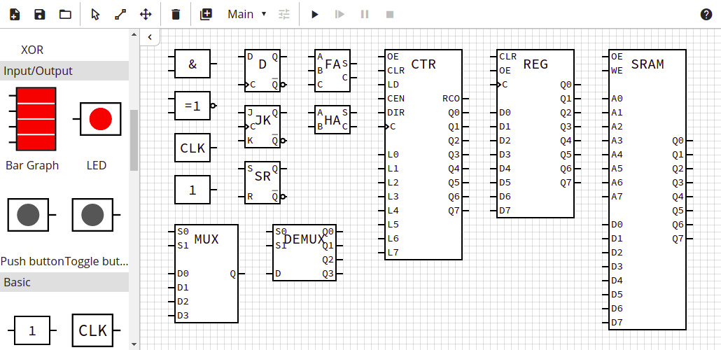
Logic Simulator maxkl de
Even though it's called an 'online' logic simulator since it can be ran conveniently in the browser, LogicEmu runs completely offline. Once the HTML and JS got fetched, it doesn't make any further connections.. ^>v< — gate and device inputs; m]w[ — inverted gate and device inputs; s — switch off; S — switch on; p — pushbutton off. Welcome to The Nand Game! You are going to build a computer starting from basic components. The game consists of a series of levels. In each level, you are tasked with building a component that behaves according to a specification. This component can then be used as a building block in the next level.